Background
I needed to add some air flow to a
Leviton Structured Media Center. However, I only wanted the fans to run when the temperature rose above a certain set-point. With some modification, the Moteino is able to control the fans and report its status back to the Moteino Gateway.
Four pin PC fans require a PWM frequency of 25KHz, but an Moteino/Arduino's default PWM frequency is significantly lower. Resolving this requires direct modification of one of the three timers built into the Arduino. However, for the case of a Moteino with an RFM69 transceiver, Timer 2 is our only real choice.
The function call used in this project's arduino sketch, which modifies Timer 2 for 25KHz operation, was obtained from the
Arduino forum.
Parts List
This application requires mounting six fans at the base of a Leviton panel with a 2"
extender bracket. Your application will likely be different. Consequently, your mounting hardware will differ.
Prerequisites
The PWM Fan Controller communicates with a Raspberry Pi, running the
Moteino Gateway. The gateway creates the 900MHz network and provides the Web UI to monitor and control the various wireless devices.
Assembly Instructions
- Wire the fan PWM pins:
- Red - 12v
- Black - Ground
- Blue - Moteino pin 3
- Wire the DHT sensor pins:
- Red - 3.3v (NOT 12 volts!)
- Black - Ground
- Yellow - Moteino pin 4
- Wire the voltage divider:
- 100 KΩ resistor wires from A7 to +12 volts
- 20 KΩ resistor wires from A7 to ground
- 0.1 µF capacitor wires from A7 to ground
- Load this PWM Fan Controller arduino sketch into the Moteino
- Mount the Moteino and PCB in a protective case
- Add the PWM Fan Control config to the moteino gateway
- Copy fanctrlr.js to the userMetrics folder on the Raspberry Pi gateway
- Copy icon_fan_controller.png to the www/images folder on the Raspberry Pi gateway
- Restart the Moteino Gateway service
Circuit Diagram
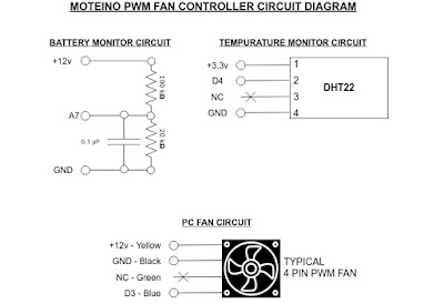
The circuit can be broken down into the following functions:
- Moteino (not shown)
- Battery monitor circuit
- Temperature monitor circuit
- PC Fan Circuit
Moteino Gateway UI
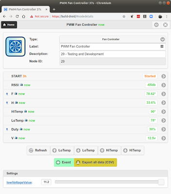 |
| PWM Fan Controller on the Moteino Gateway UI |
Once the Fan Controller is powered up, it will automatically populate on the Moteino Gateway Dashboard. Click on the newly populated Moteino then set the Type from the drop-down to PWM Fan Controller and give it friendly name. Once you set the controller type, several buttons will appear at the bottom to allow you to control the fan.
Button Definitions:
- Refresh - This forces the Moteino to immediately report its status
- LoTemp Up - Increase the minimum temperature set-point by one degree.
- LoTemp Down - Decrease the minimum temperature set-point by one degree.
- HiTemp Up - Increase the maximum temperature set-point by one degree.
- HiTemp Down - Decrease the maximum temperature set-point by one degree.
Possible Modifications
- This project does not monitor the tach output (green wire) from any of the fans. One could wire each tach output to an input on the Moteino. If the tach reading drops below a certain value, the Moteino Gateway can send a text alert.
- If the temperature hovers close to the low or high set point, the duty cycle can oscillate back and forth. This can be resolved with additional programming.
Finished Product
Sample photos of the finished product. Click to enlarge.
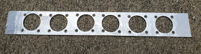 |
| Fan Mounting Plate from Strip of Aluminum |
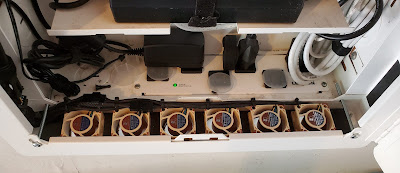 |
| Fans installed in base of Leviton panel |
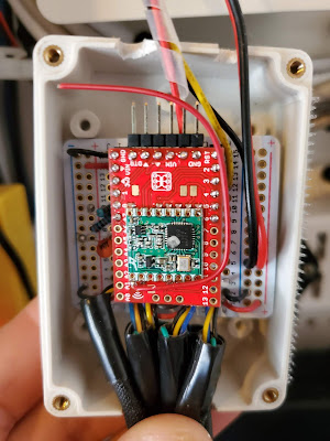 |
| Moteino mounted in small case |

 The circuit can be broken down into the following functions:


