ESP01 IoT Device for Genetec Security Center

Project Goal
The goal of this project is to build a small IoT device capable of sending temperature data to the Genetec Security Center running the IoT Plugin. The device must be inexpensive and somewhat easy to assemble and program. It must work on any wifi network, without having to directly modify config files or change software.
Parts List
- ESP01
- DHT sensor module for an ESP01
- USB barrel plug cable for power
- Optional sensor case
- USB ESP Programmer
Prerequisite Software
This blog assumes the prerequisite software has been installed:
- Genetec Security Center has been installed, is licensed, and is running
- The Genetec IoT Plugin has been installed and the Industrial IoT role has been created
- The Arduino IDE has been installed and is able to flash a (any) sample sketch to the ESP01
Program the ESP01
Load this sketch into the Arduino IDE.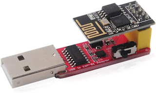
ESP01 with Programmer - Verify the sketch compiles
- Use the library manager to load any libraries that are missing, such as the WiFiManager
- Toggle the switch on the programmer towards the yellow socket to enable programming mode.
- Insert the ESP01 into the programmer then insert the programmer into a USB port on your PC
- Upload the sketch to the ESP01
- When successful, remove the ESP01 from the programmer

Assemble the Device
Carefully flip over the DHT sensor from the sensor module, without breaking the leads
Flip Over the Blue DHT Sensor
Before Attaching the ESP01- The ESP01 chip produces enough heat to skew the temperature reading of the sensor by several degrees. Flipping the DHT sensor out helps minimize this issue.
- Insert the ESP01 into the sensor module
- Place the device into the case
- Attach power to the device, observing polarity
- A least one LED should illuminate to indicate the device has power.

Configure the ESP01 for your Wifi Network
NOTE: If I have given you one of these devices pre-assembled, then this is the point in the instructions where you should start.
- Upon initial power-up, the ESP01 will go into AP mode
- Using your mobile device, attach to the wifi network called "ESPAutoConnectAP"
- No password is required
- Once connected, point your browser to 192.168.4.1
- You should be presented with the menu in the figure
- Select Configure Wifi
- Select the desired wifi network and enter the wifi password
- Enter the IP Address of your Security Center Server
- Leave the port at 42000
- Leave the Device ID set to 1, unless you have more than one device
- No two devices can have the same Device ID
- I was testing multiple devices at the time I made the screenshot below, which is why it shows a 2 for the Device ID. Ignore that. Go with 1.
- Verify all the entered information is correct, then click save
- The ESP device will reboot and attach to your wifi network
|
|


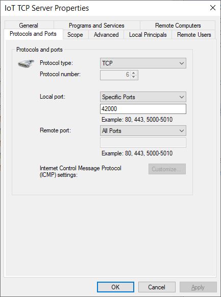
Open Port 42000 on the Windows Firewall
From the Security Center server, open the Windows Firewall
Allow Inbound TCP Port 42000
Click to Enlarge- Create an Inbound Rule to allow TCP port 42000
Configure the Genetec IoT Plugin - Create the TCP Server
Navigate to Config Tool -> Plugins Industrial IoT -> Protocols (tab)
Create TCP Server
Click to Enlarge- Create a new TCP server by clicking the green "+"
- Enter the parameters for the new TCP Server exactly as shown in the following figure.
- Click Apply to save changes

Configure the Genetec IoT Plugin - Import the Device Template
Download the appropriate device template according to your version of the IoT plugin and save it to your local drive:
Import Device TEmplate
Click to Enlarge- Navigate to Config Tool -> Plugins Industrial IoT -> Device Type tab
- Import the recently downloaded template by clicking the import button at the bottom of the screen.
- Once imported, your screen should look like the figure

Configure the Genetec IoT Plugin - Create the IoT Device from Template
Navigate to Config Tool -> Plugins Industrial IoT -> Devices tab
Add ESP Device
Click to Enlarge- Click the green "+" to add a new device
- Give the device a name
- Select ESP Device from the type dropdown
- From the TCP Server dropdown, select the previously created TCP server
- In my case the TCP Server was named ESP IoT Server
- Enter the same Device ID you used when configuring the WiFiManager
- The default Device ID is 1
- Click Add
- Finally, click the Apply button in the bottom right corner of the screen

Verify Data is Being Collected
 |
| Data from ESP Device Click to Enlarge |
new temperature data to Security Center every minute.
You can now display this device on a map and/or leverage the other features of the IoT Plugin to create events, change states, and create rules.
Troubleshooting
Builtin Web Portal
 |
| ESP01 Web Portal Click to Enlarge |
web browser to the device's ip address on your local wifi network. Use the basic menu to view device status, along with recent error or success messages.
Reconfigure WiFiManager
If any of the information provided to WiFiManager is not correct, then you will need force the device back into AP mode, to allow you to reconfigure the device. To do that, select the "resetwifi" from the ESP web portal. This will prompt for a username and password. The username is "genetec" and the password is the mac address, in all caps, without colons. This will erase the save wifi credentials then cause the device to reboot back into AP mode.
Temperature Readings Too High
If the DHT temperature sensor consistently reports higher than expected values, then the heat from the ESP01 chip is likely affecting the sensor. We can compensate by periodically sleeping the ESP01. However, the downside to this is, since the ESP01 is asleep most of the time, there is no builtin web portal one can use for troubleshooting. First verify the ESP01 is successfully reporting to Security Center. Once this is verified, reprogram the ESP01 with this sketch. You will not need to reconfigure WiFiManager configuration.
Security Considerations
These instructions are not intended for a production environment. It should be noted that this device will send data, in clear text, to the Security Center server. The ESP device's built-in web portal is standard HTTP protocol, which can be accessed by anyone on the same network, without a password.
Yes, it is possible to program the ESP01 to require authentication before accessing the built-in web portal, and it is also possible to send data to Security Center using HTTPS. However, that is a project for another day.
Comments
Post a Comment